
In this section, we explore essential problems and their solutions related to the study of circuit design and signal processing. Mastery of these topics is crucial for anyone preparing to tackle advanced studies or technical assessments in this field.
Students often encounter challenges when dealing with the building blocks of systems, such as switches, flip-flops, or combinatorial arrangements. These concepts form the foundation of complex devices, and a solid understanding is required to move on to more intricate subjects.
Comprehending the relationships between components and analyzing their behavior under different conditions can significantly improve problem-solving skills. By familiarizing oneself with various techniques and methods, it becomes easier to approach any challenge with confidence and precision.
Digital Logic Exam Questions and Answers
In this section, we dive into various problems designed to test understanding of fundamental principles in circuit analysis, switching, and signal behavior. Mastery of these challenges is essential for anyone pursuing technical knowledge in the field of electronics and systems design.
Common Problems to Practice
These problems typically focus on the core elements that shape more advanced systems. Understanding how to simplify complex scenarios and apply basic rules is key to success. Below are some of the most common types of tasks one may face:
| Task Type | Description |
|---|---|
| Simplifying Expressions | Reducing Boolean expressions using various techniques such as Karnaugh maps. |
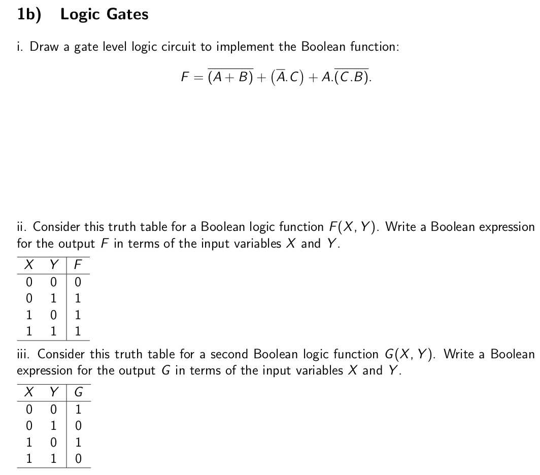
| Truth Tables | Determining the output of circuits based on inputs through tabulation. |
| Sequential Circuits | Analyzing circuits with memory elements and their state changes over time. |
| Combinational Logic | Designing circuits that output based solely on current inputs without memory. |
Techniques for Solving Problems
Solving these problems effectively requires an understanding of key methods. One must be able to identify the most efficient approach for a given task, such as using Karnaugh maps for simplification or analyzing timing diagrams for sequential circuits. By practicing these techniques, it becomes easier to break down complex problems into manageable steps.
Common Digital Logic Gate Questions

In this section, we address typical tasks that focus on the essential components of binary systems. These components are fundamental to creating circuits that perform logical operations based on input values. Understanding these basic building blocks is crucial for designing more complex systems and for mastering the principles behind their behavior.
Basic Gate Operations
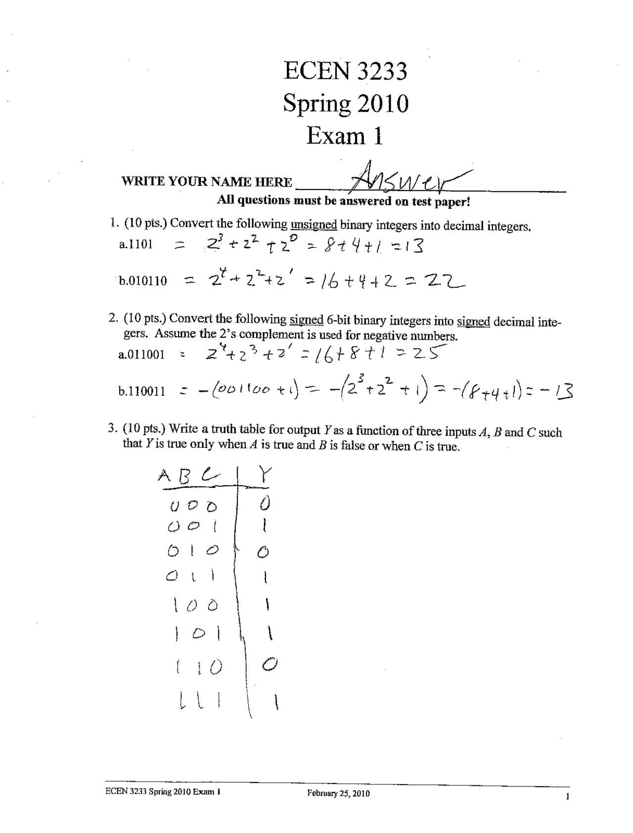
The most common challenges often involve understanding how basic gates operate individually and in combination. These gates serve as the foundation for all digital systems, and being able to work with them is a key skill.
- AND Gate: Determines if all inputs must be true for the output to be true.
- OR Gate: Outputs true if any input is true.
- NOT Gate: Inverts the input value.
- NAND Gate: The inverse of the AND gate; outputs false only when all inputs are true.
- XOR Gate: Outputs true when an odd number of inputs are true.
Typical Problems Involving Gates
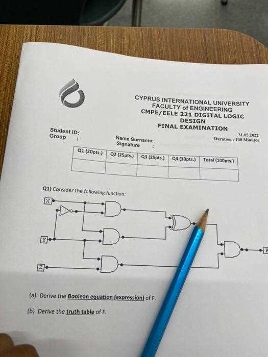
- Building a truth table for a circuit involving multiple gates.
- Simplifying a Boolean expression that includes AND, OR, and NOT gates.
- Identifying errors in a circuit based on the provided behavior.
- Combining different gates to create a desired output logic.
Boolean Algebra Practice Problems
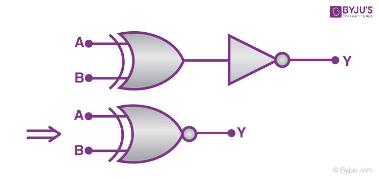
This section focuses on exercises that help strengthen your understanding of algebraic methods used in system design. These problems involve manipulating expressions, simplifying logic circuits, and applying rules to solve real-world challenges. Mastering these tasks is essential for anyone aiming to build efficient and accurate systems.
Working through these practice problems enhances your ability to handle complex expressions and develop optimized solutions for various circuits. The exercises in this section are designed to familiarize you with essential techniques, such as the use of laws and properties to simplify expressions, combine terms, and identify redundant components.
- Simplify the expression: A’B + AB’
- Apply the absorption law to the expression: (A + AB’)
- Reduce the following: (A + B)(A’ + C)
- Minimize the Boolean expression using Karnaugh maps: AB + A’C + BC
As you work through these problems, try to identify patterns that emerge from different types of simplifications and explore alternative methods to achieve the same result. This process not only reinforces the principles of Boolean algebra but also improves overall problem-solving skills in circuit design.
Combinational Circuit Question Examples
This section provides practical scenarios focused on systems where outputs depend solely on current inputs. These types of circuits are foundational in creating systems that perform specific tasks, such as data selection, arithmetic operations, and code conversion. Understanding how to analyze and design these systems is essential for developing reliable and efficient hardware solutions.
Common Problems to Solve
Below are examples of tasks that help build a strong understanding of input-output relationships in these circuits:
- Design a Multiplexer: Create a circuit that selects one of several inputs to pass to the output based on control signals.
- Simplify an Adder: Combine multiple full adders to build a multi-bit addition system.
- Create a Decoder: Design a circuit that activates one specific output line based on binary input combinations.
- Analyze an Encoder: Examine how an input signal set can be converted into a binary output.
Key Truth Tables to Study
Understanding truth tables is a fundamental skill for analyzing how different inputs affect the outcome in various systems. These tables are used to map all possible input combinations to their corresponding output, providing clarity and structure for troubleshooting and circuit design. Mastery of these tables is crucial for anyone working with systems that rely on conditional logic.
Basic Operations to Master
The following operations form the basis for building more complex systems. Familiarity with their truth tables is essential:
- AND: The output is true only if all inputs are true.
- OR: The output is true if at least one input is true.
- NOT: The output is the inverse of the input.
Advanced Operations to Explore
Once the basic functions are understood, studying more complex operations is important:
- XOR: The output is true if the number of true inputs is odd.
- NAND: The output is false only when all inputs are true.
- Full Adder: Calculates the sum of three inputs, including carry bits.
By thoroughly studying these tables, you’ll gain a deeper understanding of how input values determine the output, making it easier to design, simplify, and troubleshoot systems.
Understanding Logic Minimization Techniques

Minimization techniques are essential for optimizing systems by reducing the complexity of expressions while maintaining their functionality. These methods focus on eliminating redundant components, streamlining designs, and improving overall efficiency. Mastering these techniques is crucial for simplifying circuits and ensuring that systems operate at their best with minimal resources.
Common Methods for Minimization
Several key techniques are frequently used to simplify Boolean expressions and reduce the number of components in a system:
- Karnaugh Maps: A graphical method to simplify expressions by grouping terms that differ by only one variable.
- Quine–McCluskey Algorithm: A tabular method used for minimization, often applied in more complex systems where Karnaugh maps are less practical.
- Boolean Algebra Simplification: The process of using standard algebraic rules to reduce expressions directly.
Practical Applications of Minimization
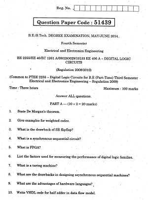
By applying these techniques, you can achieve significant reductions in the number of terms, gates, or switches required in a design. Some typical examples include:
- Designing faster and more efficient digital circuits.
- Reducing the physical space required for components in hardware design.
- Improving system reliability by minimizing the number of possible failure points.
Utilizing minimization strategies allows for more efficient, cost-effective, and scalable solutions in system design and problem-solving.
Flip-Flops and Sequential Circuits Queries
Sequential circuits are systems where the output depends not only on the current input but also on past states. These circuits use memory elements, such as flip-flops, to store information and create systems that can perform tasks over time, like counting, timing, and state transitions. Understanding how these components work together is key to building systems that require memory and time-based decisions.
Flip-flops are the building blocks of sequential circuits. They store a single bit of information and can change states based on specific conditions, making them ideal for use in registers, counters, and more complex systems. By mastering the behavior and operation of flip-flops, you can design reliable circuits that respond to both present inputs and previous outputs.
- SR Flip-Flop: A basic memory element that stores a single bit and changes its state based on the inputs.
- D Flip-Flop: A more stable type of flip-flop, where the state is determined by a single input, making it easier to use in clocked systems.
- JK Flip-Flop: A versatile flip-flop that can toggle, set, or reset its state based on its inputs.
- T Flip-Flop: A flip-flop that toggles its output with each clock pulse, commonly used in counters.
By understanding the behavior of these memory elements, you can design more complex systems like registers, counters, and finite state machines that operate based on sequences of inputs and outputs, which are essential in many digital systems and applications.
Multiplexers and Demultiplexers Practice
Multiplexers and demultiplexers are essential components in modern communication and data processing systems. These devices allow for efficient data routing by either selecting one input from many (multiplexing) or distributing a single input to multiple outputs (demultiplexing). Understanding how to design, configure, and apply these systems is key to creating efficient and scalable digital architectures.
Multiplexer Design Exercises
In the case of multiplexers, the goal is to route one of several input signals to a single output line based on control signals. Common exercises include:
- Design a 4-to-1 Multiplexer: Create a system that selects one of four input lines based on two control signals.
- Implement a Multiplexer Using Logic Gates: Build a multiplexer from basic gates and understand how each part contributes to the final design.
- Extend a 2-to-1 Multiplexer to Handle More Inputs: Practice scaling up the design to handle more inputs and control signals.
Demultiplexer Design Practice
For demultiplexers, the task is to take a single input and route it to one of many output lines. Common exercises include:
- Design an 1-to-4 Demultiplexer: Create a system that routes one input to one of four outputs based on two control signals.
- Build a Demultiplexer with Logic Gates: Use basic gates to implement a demultiplexer and analyze how different components work together to route the input.
- Simulate Data Routing: Understand how to manage data flow and timing when using demultiplexers in practical applications.
Through these exercises, you’ll gain hands-on experience in designing and analyzing multiplexers and demultiplexers, two fundamental components used in data handling, signal routing, and communication systems.
Binary Arithmetic and Operations Overview
Binary arithmetic forms the foundation for numerous systems that process data in computers and other electronic devices. By understanding how binary numbers are manipulated, you can efficiently handle calculations and operations in digital systems. These operations are similar to those performed with decimal numbers but are based on a two-symbol system, where only 0 and 1 are used.
In this section, we explore the key operations involved in binary arithmetic, such as addition, subtraction, multiplication, and division. Each of these operations follows specific rules that ensure the correct manipulation of binary numbers, which are critical for both simple and complex computations in computer systems.
Basic Binary Operations
The most fundamental operations in binary arithmetic include:
- Binary Addition: Involves adding two binary numbers, carrying over any excess when the sum exceeds 1.
- Binary Subtraction: Follows similar principles to decimal subtraction, often using the method of borrowing.
- Binary Multiplication: A process similar to decimal multiplication but requires the repeated addition of shifted values.
- Binary Division: Involves dividing binary numbers using the long division method, with careful attention to remainders.
Advanced Binary Operations
In addition to the basic operations, there are more advanced binary functions that enhance the capability of digital systems:
- Bitwise Operations: These operations include bitwise AND, OR, XOR, and NOT, which manipulate individual bits of binary numbers.
- Shifting: Shifting operations move the digits of binary numbers left or right, effectively multiplying or dividing by powers of two.
- Two’s Complement: A method for representing negative binary numbers and performing efficient subtraction in binary form.
By mastering these binary operations, you can efficiently solve a wide range of problems encountered in computing, ranging from basic arithmetic to complex algorithms and system designs.
How to Solve Karnaugh Maps
When dealing with complex Boolean expressions, simplifying them into more manageable forms is essential for designing efficient digital systems. One of the most effective tools for this simplification is a graphical method known as a Karnaugh map. This method provides a visual representation of Boolean functions, making it easier to identify patterns and reduce expressions with minimal effort.
A Karnaugh map consists of a grid where each cell represents a combination of input variables, and the values within the grid correspond to the output of a Boolean function. By grouping adjacent cells with similar values, you can identify opportunities for simplification, reducing the number of terms and operations required to represent the function.
Steps to Solve Karnaugh Maps
Follow these steps to simplify a Boolean expression using a Karnaugh map:
- Set Up the Map: Create a grid based on the number of input variables. For n variables, you’ll need a 2^n cell map. Label the rows and columns according to the combinations of input variables.
- Populate the Cells: Fill the grid with values that represent the output of the Boolean function for each input combination. Typically, these values are derived from a truth table.
- Group the Ones: Look for adjacent cells containing 1s. Group them into rectangles or squares, ensuring that the number of cells in each group is a power of 2 (1, 2, 4, 8, etc.). The larger the group, the greater the simplification.
- Simplify the Expression: For each group of ones, write a product term that corresponds to the variables that remain constant across the group. Then, combine all the simplified product terms to form the final expression.
Example of Simplification
Consider a 3-variable Boolean function. The map will have 8 cells. After filling the grid with output values, you can group adjacent 1s, simplify them, and derive the simplest Boolean expression. The more groups you can make, the fewer terms you’ll have in the final expression.
By mastering the Karnaugh map technique, you can simplify complex Boolean functions, streamline circuit designs, and improve the efficiency of digital systems.
Common Errors in Digital Logic Exams
When tackling complex problems related to binary systems, circuits, or Boolean expressions, students often make a few key mistakes that hinder their ability to perform well. These errors typically stem from misunderstandings of fundamental concepts or misapplication of techniques used to simplify or solve problems. Recognizing and avoiding these common pitfalls can significantly improve performance and understanding.
In this section, we explore some of the most frequent mistakes that occur during problem-solving in this field, offering tips on how to avoid them. By being aware of these issues, you can improve your approach, accuracy, and efficiency when tackling assignments or assessments.
Common Mistakes to Avoid
- Incorrect Use of Boolean Operations: Misinterpreting the rules of Boolean algebra, such as failing to apply the correct identity properties or not simplifying expressions properly, can lead to incorrect results.
- Overlooking Simplification Opportunities: Skipping the process of simplifying expressions using methods like Karnaugh maps or Boolean algebra often results in unnecessarily complex solutions that are difficult to manage and understand.
- Failure to Draw Accurate Diagrams: When working with circuits, drawing accurate and clear circuit diagrams is essential. Inaccurate or unclear diagrams can cause confusion and lead to incorrect solutions.
- Confusing Truth Tables: A common issue is misreading or incorrectly filling out truth tables. Always ensure the values are accurate for each combination of inputs to avoid propagation of errors throughout the problem.
- Neglecting Edge Cases: Sometimes, students focus on the most common cases and overlook the “edge” scenarios, which can cause errors, particularly when working with more complex Boolean functions or circuit behaviors.
By addressing these common errors and practicing careful attention to detail, you can improve your problem-solving skills and avoid pitfalls during assessments, ensuring better results and deeper understanding of the material.
Tips for Mastering Digital Logic Topics
To achieve proficiency in the realm of binary systems, circuit design, and Boolean functions, it’s essential to approach the subject with a structured and strategic mindset. Mastery of these topics requires a combination of understanding the theoretical concepts and practicing problem-solving techniques. With focused effort, you can develop a deep understanding that will enhance your ability to design systems and solve complex tasks effectively.
This section provides key strategies to help you master the fundamental topics in this field, from simplifying Boolean expressions to designing efficient circuits. These tips will guide you toward a solid grasp of the concepts and boost your confidence in applying them in practical scenarios.
Study Strategies for Success
- Understand Core Concepts: Before diving into complex problems, ensure that you have a firm grasp of the basic principles, such as truth tables, binary arithmetic, and common circuit types. A solid foundation will make advanced topics easier to comprehend.
- Practice Regularly: The more problems you solve, the more familiar you become with various techniques and methods. Set aside time each day to work on practice problems to reinforce your learning and gain experience with different problem types.
- Visualize Solutions: When working with circuits or Boolean expressions, try to visualize the process step by step. Drawing diagrams, using Karnaugh maps, or sketching circuits will help you internalize the concepts and improve your problem-solving skills.
- Use Online Resources: Take advantage of online tools, tutorials, and forums to further your understanding. These resources can provide different perspectives and explanations, making it easier to grasp challenging concepts.
- Review Mistakes: Don’t just focus on getting the right answers. Analyze the mistakes you make and understand why they happened. Learning from your errors will help you avoid similar mistakes in the future and deepen your understanding of the material.
By implementing these tips into your study routine, you can improve both your theoretical knowledge and practical problem-solving skills, ultimately mastering the key topics in this field.
Memory Elements in Digital Logic
Memory elements play a crucial role in storing and manipulating data within circuits. These components allow systems to retain information over time, which is essential for tasks like state retention and sequential processing. By understanding the function and application of these memory elements, you can gain insights into how complex systems manage data storage, transitions, and logic states.
In this section, we will explore the primary types of memory elements commonly used in circuits. These include flip-flops, latches, registers, and more. Each of these components serves a unique purpose in maintaining data integrity within a system.
Types of Memory Elements
- Flip-Flops: These are bistable devices used to store a single bit of information. Flip-flops are fundamental for building sequential circuits and can be configured to hold data based on specific triggers or clock signals.
- Latches: Similar to flip-flops, latches are bistable circuits that retain a state but differ in how they respond to control signals. They are often used for temporary data storage in less clock-dependent applications.
- Registers: These are groups of flip-flops that can store multiple bits of data, often used for holding intermediate results during processing. Registers are key components in processors and memory systems.
- Memory Arrays: These are larger collections of memory elements arranged in specific structures to store large amounts of data efficiently. They are often used in RAM and other memory systems.
Example of Memory Element Setup
To illustrate how memory elements work, consider the following example of a flip-flop table:
| Clock Input | Input Value | State After Clock |
|---|---|---|
| 0 | 1 | Previous State |
| 1 | 1 | 1 |
| 1 | 0 | 0 |
This table demonstrates the behavior of a basic flip-flop. When the clock input is 0, the state remains the same. Upon receiving a clock pulse (1), the state will change according to the input value.
By mastering memory elements, you can understand how circuits perform sequential operations, hold states, and work with temporary data during processing tasks. This knowledge is fundamental for designing complex systems such as processors, data storage devices, and control systems.
Analysis of Logic Circuit Design Problems
Designing circuits that perform specific tasks requires careful analysis and consideration of how components interact. Often, designers must troubleshoot and refine their circuits to ensure they meet desired specifications, which can involve identifying inefficiencies or errors in the initial design. Analyzing circuit behavior is a crucial part of the process, helping engineers optimize performance and ensure reliability.
In this section, we will break down common challenges encountered during circuit design. These challenges include simplifying complex designs, reducing errors in the configuration, and improving the efficiency of the system by optimizing the use of components. Understanding how to analyze and address these issues is essential for creating robust and functional circuits.
Common Problems in Circuit Design
- Complexity Management: As circuits grow in complexity, managing the number of components and ensuring correct interactions can become increasingly difficult. A well-designed layout is essential for minimizing complexity while maintaining functionality.
- Minimizing Redundancy: Redundant components or connections can increase the cost and size of a circuit. Streamlining the design to use fewer parts without compromising performance is a key aspect of optimization.
- Signal Timing Issues: Delays and improper timing between components can lead to errors in circuit operation. Timing must be carefully analyzed to ensure that signals arrive in the correct order and at the right time.
- Power Consumption: Inefficient use of power can lead to unnecessary energy consumption, which is especially problematic in portable or battery-powered devices. Efficient design practices help reduce power usage.
- Fault Tolerance: Ensuring the circuit can function correctly even when certain parts fail is important for high-reliability systems. Analyzing possible failure modes and designing with fault tolerance in mind can prevent breakdowns.
Strategies for Effective Analysis
- Simulations: Using simulation tools to model circuit behavior allows designers to visualize how components interact and detect potential issues before physical implementation.
- Component Testing: After assembling a design, testing each component individually can help identify and resolve problems before integrating them into a complete system.
- Redundancy Checks: Double-checking circuit paths for redundancies helps streamline the design and reduce unnecessary parts that increase cost and complexity.
- Timing Analysis: Thorough analysis of timing constraints ensures that all components are synchronized and working correctly, preventing errors due to incorrect signal sequencing.
By mastering the analysis of design problems, engineers can develop circuits that are both efficient and reliable. Identifying potential pitfalls early in the design process can save time and resources, ultimately leading to more effective solutions.
Timing Diagrams and Their Significance
Timing diagrams are essential tools used to illustrate the sequence of signals within a system over time. They provide a clear, visual representation of how various signals or states in a circuit interact and evolve as time progresses. By observing these diagrams, engineers can ensure that components are operating correctly and that the desired system behavior is achieved without timing conflicts or errors.
Understanding the significance of timing diagrams is crucial for diagnosing issues, optimizing performance, and ensuring reliability in complex systems. These diagrams help identify potential issues such as timing mismatches, delays, or synchronization problems between different parts of a circuit. Proper analysis of timing diagrams can prevent costly mistakes and improve the overall efficiency of the system.
Key Components of Timing Diagrams
- Signal Transitions: Timing diagrams show the state changes of various signals over time, allowing engineers to track how inputs and outputs evolve at each clock cycle or event.
- Clock Cycles: A key feature of these diagrams is the clock cycle, which marks the reference points for when changes in signals should occur. Proper alignment with clock cycles is critical for accurate operation.
- Control Signals: These diagrams also highlight control signals, which dictate the behavior of specific components within a system. They help engineers verify that these signals are reaching the correct states at the proper time.
- Delays: By showing the time intervals between events, timing diagrams can reveal potential delays that may cause problems, such as signals arriving out of sync or taking too long to propagate.
Why Timing Diagrams Matter
- System Optimization: Timing diagrams help engineers identify areas where a system might be slowed down or where resources could be better allocated, leading to improved system performance.
- Debugging: When circuits do not behave as expected, timing diagrams are invaluable for pinpointing where the timing issue lies, helping engineers isolate problems faster.
- Synchronization: Proper synchronization of signals is key for smooth operation, and timing diagrams provide a clear view of whether different components are working together as intended.
- Failure Prevention: By understanding the timing of signals, engineers can predict potential failures, such as timing conflicts, which could otherwise cause malfunction or damage to the system.
In summary, timing diagrams are an indispensable tool for anyone involved in designing, troubleshooting, or optimizing systems. They provide insight into the functioning of a circuit over time and allow for the identification and correction of issues related to signal sequencing, delays, or synchronization, ensuring that systems perform reliably and efficiently.
Digital Logic Exam Question Strategies
Approaching assessments that test your knowledge of circuit design and system analysis requires a methodical approach. Knowing how to tackle challenges efficiently can make a significant difference in your performance. Whether you’re solving for Boolean expressions or analyzing timing sequences, understanding how to break down problems is key to success.
To excel, it’s important to develop strategies that will help you work through various topics effectively. By focusing on the core principles, practicing common problem types, and managing your time wisely, you can increase your chances of success.
Effective Problem-Solving Techniques
- Read Carefully: Always start by reading the problem carefully to understand what is being asked. Make sure you know exactly what information is provided and what needs to be determined before proceeding.
- Break Down Complex Problems: If the problem appears complicated, break it down into smaller, more manageable parts. This will help you focus on one aspect of the task at a time, reducing the chance of overlooking key details.
- Use Diagrams: Whenever possible, sketch diagrams or truth tables to visualize the relationships between components or signals. Diagrams can help clarify your understanding and make it easier to find the solution.
- Work Through Examples: Prior to the test, practice solving problems similar to those you might encounter. This will help you familiarize yourself with common types of challenges and the best techniques to address them.
Time Management Tips
- Allocate Time Wisely: Allocate a set amount of time to each section of the assessment. Try to avoid spending too much time on any one problem–move on if you’re stuck and return to it later.
- Start with What You Know: Begin with the problems that seem easiest to you. This will help you build confidence early on and secure easy points before tackling more difficult challenges.
- Review Your Work: If time permits, review your answers to ensure you haven’t missed any key steps. Double-check calculations and ensure all parts of the problem have been addressed thoroughly.
- Don’t Rush: While time management is important, rushing can lead to careless mistakes. Focus on clarity and accuracy, especially when dealing with complex steps or calculations.
With a combination of solid problem-solving techniques, practice, and effective time management, you can improve your ability to tackle any challenge that comes your way. The key to success lies in staying organized, being methodical, and understanding the core concepts behind the tasks you’re asked to complete.